Post by shoob on Oct 14, 2011 1:35:57 GMT -5
im gonna discuss porting on the 16v heads. reason being.....theres not much room in the way of improvement on the flow characateristics (sp*) on the 20v's other than cleaning up the factory casting marks and improving the valve seats , but ill get to all that terminology in this thread.
1. terminology-
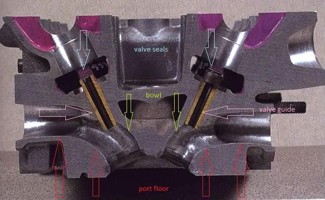
bowl - the area right below the valve seat, the rounded part that surrounds the valve guide.
valve guide- bronze or brass sleeve that holds the valve stems of the valves in theyre places in the head.
port floor- the bottom of the port inlet leading to the valve seat.
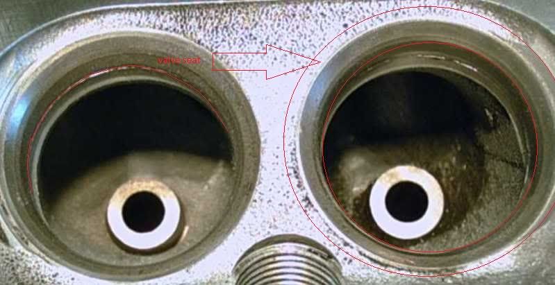
valve seat- the "seat" milled into the head that the valve rest on while in the closed position.
valve seal- located on the tops of the valve guides, this is a little rubber seal/gasket that keeps enough oil in the valve guide to keep it lubricated while the valve stem is moving inside, but keeps majority of oil out to avoid carbon scalling from ruining your chambers and ports.
divider- exactly what it sounds like , the little partition between each individual valve port inside the port runner.
port runner- the entrance of the port on the head before the divider. a "staging" area for air flow , if you will.
port cieling/roof- the top of the port rounding to the bowl.
coolant jacket- something you do not want to hit while porting.
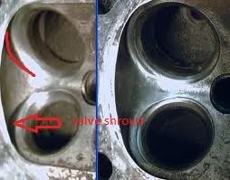
valve shroud- in the combustion chamber , these raised ridges help to direct the air/fuel mixture to optimum location in the combustion chamber on low velocity setups.
now that all that is out of the way, heres some pointing diagrams to help explain.
ok with all that out of the way we'll begin. what is porting? porting is removing the inefficientcies from a factory cast head. when a head is cast at the factory its done in mass production, so too careful of attention isnt taken. as long as it passes the quality control , it ends up on your engine in your car. also the term "port and polish" is taken the wrong way. polishing only consist of the exhaust ports , where porting is primarily performed on the intake ports.
when porting a "g" head theres quite a few areas for improvement. where as the "g" head is great in terms of design (thank yamaha) its manufacturing is a different story.
the first thing to call attention to is where the bowl meets the valve seat. this area is always guaranteed a poor alignment on every largeport head looked at. in this area blending is the best option. by blending youll be improving flow alot more than you think. if you have youre head off or a "g" head lying around, feel this for yourself....run your finger around the inside of the valve seat leading to the bowl and you will feel the raised "edge" under the valve seat. this comes from poor alignment once again at the manufacturer. youll want to use a demel tool with a stone capable of removing the aluminum material , but not gouging it out. keep a smooth movement and dont hold the tool in one spot for too long. in the pic below ive got this "edge" to be blended away marked with the red line.

once blended away it should look something like this.... (the bottom pic w/ blue light)

youll want to do this on the exhaust bowls as well. below a few more pictures from different angles. the will also show areas in need of blending.
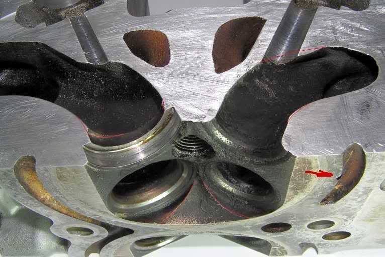
^in this picture im using the intake port as an example. in this pic you can clearly see the casting imperfection behind the valve seat that im talking about. upon removing and blending that ridge with the bowl youll not ive got a little of the port floor in the area to be blended as well. also note the top side of the valve seat in that pic ive also got an area marked in need of blending. this is something youll have to feel around the whole bowl for. 99% of the time the imperfection will be off set on one side of the valve seat than the other.
so this is the first step to mild street porting and getting a better flow. this is something a beginner can do to see noticable difference in throttle responce. power and fuel economy as well. let me add a note here!!! be very careful when working around the valve seats and be sure not to nick them, or scar them in any way.....it will suck donkey testicle as an end result.
ok now that youve done this and your starting to feel comfortable with your rotary tool. lets move to something a little more advanced. the port floors and ceilings. ill include a pic below to explain the areas that need to be touched up. while you cant see these areas to well , and you cant cross section your head like the pic shown , you can actually feel the areas in need of removal.
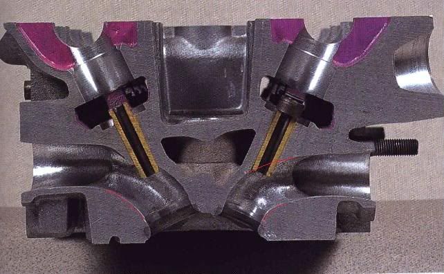
^in this picture youll see the parts of the intake and exhaust port floors that could use some work. also note the are right before my red lines on the intake side that area can be dropped a little as well. also note on the exhaust side youll see i got a red line going right thru the valve guide. thats because some people actually cut theyre valve guide short on the exhaust side to reduce , and do this with no adverse effects.
also while looking on the left and right sides of your ports youll notice casting marks. blend them away , get rid of them. you want to make your ports as free flowing as possible.
now lets move on to something a little more advanced but still not proffesional level. valve shrouds. valve shrouds are on the outside edges of the valve seats in the combustion chambers. on a head these "shrouds" help aid in the swirling of the a/f mixture. for better fuel miledge, and a more efficient burn to keep pinging to a minumum, emissi0ns purposes (also remember theres a catalytic converter downstream, dont wanna clog that) and maximizing hp in a low volume engine.
this is something that should really only be worried about after installing decent cams or ITB's, raised compression, forced intuction or nitrous. since your increasing velocity entering your cylinder not only with the now clean ports. more air entering the chamber whether it be any one or all 3 (=]) of the previously mentioned methods, theres no need for this now "drag" that is in the path of all that free flowing a/f mixture. theres an argument here thats brought up.....cylinder washing. too much fuel spraying on the cylinder wall causing less oil to be present between the piston ring and cylinder wall. but thats getting into serious build area anyway, like formula atlantic territory.

you dont wanna go crazy here , just remove the sharp edge , and round out the shroud. when doing this you want to put an old valve in the seat your working around because the rotary tool is impossible to hold that steady , that close. another deep explanation here. you dont want to completely remove this unless your preppared to start chamber matching. this involves a few specialty tools. reason being , if you dig into the chamber , then youll start having different comp. ratios across the cylinders. so stay way from getting overly confident and completely removing any signs of them. its ok to still have a slight hump there. below are some example pics ....


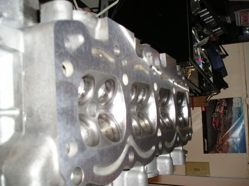
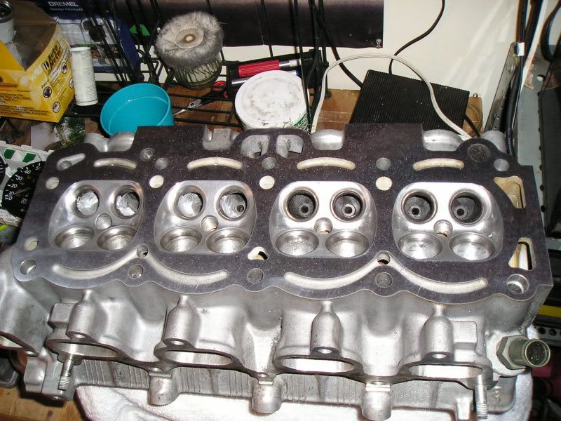
ok lets talk about finishing. rule one...never polish an intake port. ive always finished mine in 60-80 grit. reason being , you dont want the fuel collecting on the wall of the ports instead of staying atomized and entering the cylinder. example , look at the smooth surface of a car with fresh paint (had to add the "fresh" part in there, round here "whats that?" lmao =]) the next time it rains, then look at the surface of one of our cars. notice the new car has water beaded all over it , and ours is just wet , but with no beaded water, thats the same effect. now in the combustion chamber and exhaust ports where high heat and carbon is present, you want to polish these surfaces. carbon cant stick to the surface when polished. and air , especially hot air is gonna take the path of least resistance. free flowing , very low turbulance is gonna also help for a better scavenging effect. below ill show the best areas to polish in the combustion chambers. as far as the exhaust ports...all of it.
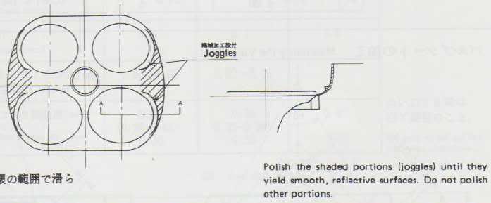
there you have it a beginner can do it. if youre having any dought , go get a scrap $20 head and practice a few times on it. better than destroying the only head you have because of a mistake or slip. if you feel overwhelmed or nervous, just remember these heads have been around for 20 years some of them more , they are a dime a dozen and everywhere and arent expensive at all.
also dont go crazy on removing material on your mainly stock engine, if you do congrats you just created one of those $20 scrap heads. remember even mass produced, no 2 heads are the same in the way they are cast, so cooling jacket on the 3rd port you hog might be a little closer than the 1st two. so in a street port moderation is key. a stock head is better than an overported head. you will lose power if you remove too much material , because velocity is out the window. the head has to maintain a nice balance between volume and velocity in order to make the best power.
for more "g" head tricks im currently having to replace the head gasket on my bluetop , and im gonna do some work on it as well as soon as i get it back from the hot tank. ill be sure to update and show lots of in-progress pics as well , ill also cover things such as cam selection, LSA (lobe seperation angle in twin cam engines), adjustable timing gears, and other head related things.
this guy covers alot of things covered here. in his video he does almost a step by step walk thru of everything mentioned. also note , those combustion chambers look familiar?
i would also like to thank billzilla.org and oldskewltoy from club4ag.com for letting me use their pictures to draw all over and exploit here =p
1. terminology-
bowl - the area right below the valve seat, the rounded part that surrounds the valve guide.
valve guide- bronze or brass sleeve that holds the valve stems of the valves in theyre places in the head.
port floor- the bottom of the port inlet leading to the valve seat.
valve seat- the "seat" milled into the head that the valve rest on while in the closed position.
valve seal- located on the tops of the valve guides, this is a little rubber seal/gasket that keeps enough oil in the valve guide to keep it lubricated while the valve stem is moving inside, but keeps majority of oil out to avoid carbon scalling from ruining your chambers and ports.
divider- exactly what it sounds like , the little partition between each individual valve port inside the port runner.
port runner- the entrance of the port on the head before the divider. a "staging" area for air flow , if you will.
port cieling/roof- the top of the port rounding to the bowl.
coolant jacket- something you do not want to hit while porting.
valve shroud- in the combustion chamber , these raised ridges help to direct the air/fuel mixture to optimum location in the combustion chamber on low velocity setups.
now that all that is out of the way, heres some pointing diagrams to help explain.


ok with all that out of the way we'll begin. what is porting? porting is removing the inefficientcies from a factory cast head. when a head is cast at the factory its done in mass production, so too careful of attention isnt taken. as long as it passes the quality control , it ends up on your engine in your car. also the term "port and polish" is taken the wrong way. polishing only consist of the exhaust ports , where porting is primarily performed on the intake ports.
when porting a "g" head theres quite a few areas for improvement. where as the "g" head is great in terms of design (thank yamaha) its manufacturing is a different story.
the first thing to call attention to is where the bowl meets the valve seat. this area is always guaranteed a poor alignment on every largeport head looked at. in this area blending is the best option. by blending youll be improving flow alot more than you think. if you have youre head off or a "g" head lying around, feel this for yourself....run your finger around the inside of the valve seat leading to the bowl and you will feel the raised "edge" under the valve seat. this comes from poor alignment once again at the manufacturer. youll want to use a demel tool with a stone capable of removing the aluminum material , but not gouging it out. keep a smooth movement and dont hold the tool in one spot for too long. in the pic below ive got this "edge" to be blended away marked with the red line.

once blended away it should look something like this.... (the bottom pic w/ blue light)

youll want to do this on the exhaust bowls as well. below a few more pictures from different angles. the will also show areas in need of blending.

^in this picture im using the intake port as an example. in this pic you can clearly see the casting imperfection behind the valve seat that im talking about. upon removing and blending that ridge with the bowl youll not ive got a little of the port floor in the area to be blended as well. also note the top side of the valve seat in that pic ive also got an area marked in need of blending. this is something youll have to feel around the whole bowl for. 99% of the time the imperfection will be off set on one side of the valve seat than the other.
so this is the first step to mild street porting and getting a better flow. this is something a beginner can do to see noticable difference in throttle responce. power and fuel economy as well. let me add a note here!!! be very careful when working around the valve seats and be sure not to nick them, or scar them in any way.....it will suck donkey testicle as an end result.
ok now that youve done this and your starting to feel comfortable with your rotary tool. lets move to something a little more advanced. the port floors and ceilings. ill include a pic below to explain the areas that need to be touched up. while you cant see these areas to well , and you cant cross section your head like the pic shown , you can actually feel the areas in need of removal.

^in this picture youll see the parts of the intake and exhaust port floors that could use some work. also note the are right before my red lines on the intake side that area can be dropped a little as well. also note on the exhaust side youll see i got a red line going right thru the valve guide. thats because some people actually cut theyre valve guide short on the exhaust side to reduce , and do this with no adverse effects.
also while looking on the left and right sides of your ports youll notice casting marks. blend them away , get rid of them. you want to make your ports as free flowing as possible.
now lets move on to something a little more advanced but still not proffesional level. valve shrouds. valve shrouds are on the outside edges of the valve seats in the combustion chambers. on a head these "shrouds" help aid in the swirling of the a/f mixture. for better fuel miledge, and a more efficient burn to keep pinging to a minumum, emissi0ns purposes (also remember theres a catalytic converter downstream, dont wanna clog that) and maximizing hp in a low volume engine.
this is something that should really only be worried about after installing decent cams or ITB's, raised compression, forced intuction or nitrous. since your increasing velocity entering your cylinder not only with the now clean ports. more air entering the chamber whether it be any one or all 3 (=]) of the previously mentioned methods, theres no need for this now "drag" that is in the path of all that free flowing a/f mixture. theres an argument here thats brought up.....cylinder washing. too much fuel spraying on the cylinder wall causing less oil to be present between the piston ring and cylinder wall. but thats getting into serious build area anyway, like formula atlantic territory.

you dont wanna go crazy here , just remove the sharp edge , and round out the shroud. when doing this you want to put an old valve in the seat your working around because the rotary tool is impossible to hold that steady , that close. another deep explanation here. you dont want to completely remove this unless your preppared to start chamber matching. this involves a few specialty tools. reason being , if you dig into the chamber , then youll start having different comp. ratios across the cylinders. so stay way from getting overly confident and completely removing any signs of them. its ok to still have a slight hump there. below are some example pics ....


ok lets talk about finishing. rule one...never polish an intake port. ive always finished mine in 60-80 grit. reason being , you dont want the fuel collecting on the wall of the ports instead of staying atomized and entering the cylinder. example , look at the smooth surface of a car with fresh paint (had to add the "fresh" part in there, round here "whats that?" lmao =]) the next time it rains, then look at the surface of one of our cars. notice the new car has water beaded all over it , and ours is just wet , but with no beaded water, thats the same effect. now in the combustion chamber and exhaust ports where high heat and carbon is present, you want to polish these surfaces. carbon cant stick to the surface when polished. and air , especially hot air is gonna take the path of least resistance. free flowing , very low turbulance is gonna also help for a better scavenging effect. below ill show the best areas to polish in the combustion chambers. as far as the exhaust ports...all of it.

there you have it a beginner can do it. if youre having any dought , go get a scrap $20 head and practice a few times on it. better than destroying the only head you have because of a mistake or slip. if you feel overwhelmed or nervous, just remember these heads have been around for 20 years some of them more , they are a dime a dozen and everywhere and arent expensive at all.
also dont go crazy on removing material on your mainly stock engine, if you do congrats you just created one of those $20 scrap heads. remember even mass produced, no 2 heads are the same in the way they are cast, so cooling jacket on the 3rd port you hog might be a little closer than the 1st two. so in a street port moderation is key. a stock head is better than an overported head. you will lose power if you remove too much material , because velocity is out the window. the head has to maintain a nice balance between volume and velocity in order to make the best power.
for more "g" head tricks im currently having to replace the head gasket on my bluetop , and im gonna do some work on it as well as soon as i get it back from the hot tank. ill be sure to update and show lots of in-progress pics as well , ill also cover things such as cam selection, LSA (lobe seperation angle in twin cam engines), adjustable timing gears, and other head related things.
this guy covers alot of things covered here. in his video he does almost a step by step walk thru of everything mentioned. also note , those combustion chambers look familiar?
i would also like to thank billzilla.org and oldskewltoy from club4ag.com for letting me use their pictures to draw all over and exploit here =p

